
Scan-To-Plan™ An effective solution to your laser scanning needs.
Scan and Register
Have us process and register your scan data. Our 3 stage registration and alignment process provides you with an accurate low tolerance point cloud alignment.
- Stage 1: Pre-align scans using Faro® Scene.
- Stage 2: Perform cloud to cloud constraints in Leica Cyclone of the pre-aligned scans.
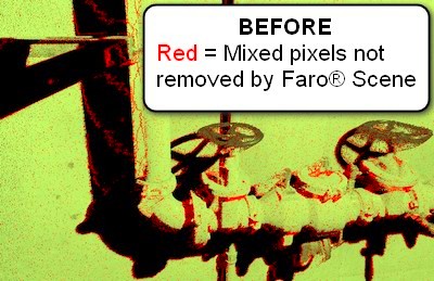
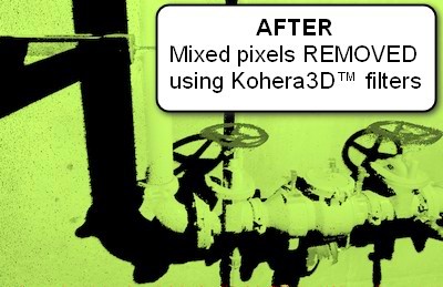
- Stage 3: Evaluate registration and data overlap using Kohera3D™ proprietary software. Here we also perform the following:
-
- Advanced filtering of mixed pixels not removed by Faro® Scene.
- View registration overlap. Fine tune scan alignment and correct as needed.
- Finalize point cloud registration and set site coordinates.
We can filter your scan data or you can purchase Kohera3D™ Piping with scan filters here
Isolate and Classify
Items in the point cloud can be layered into vertex groups (unlimited individual categories of your choice), such as walls, floors, equipment, and piping systems. This provides users with a "smart" point cloud where items can be turned on/off and viewed separately from surrounding scan data. These layers improve visualization and system identification.
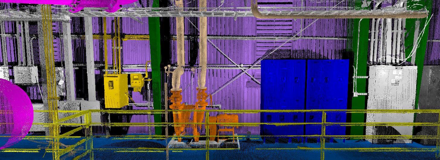
Walls, floor, piping, and electrical isolated into individual layers
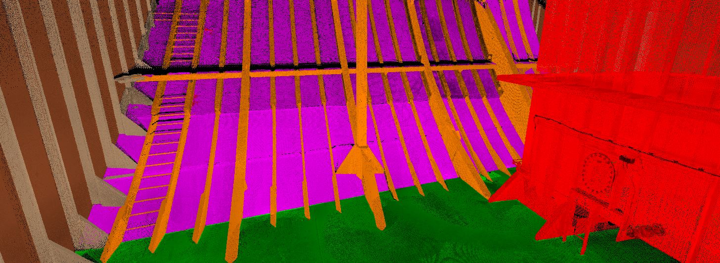
A ship's bulkheads, structure, and equipment isolated into individual layers
More details about Point Cloud Isolation and Classification
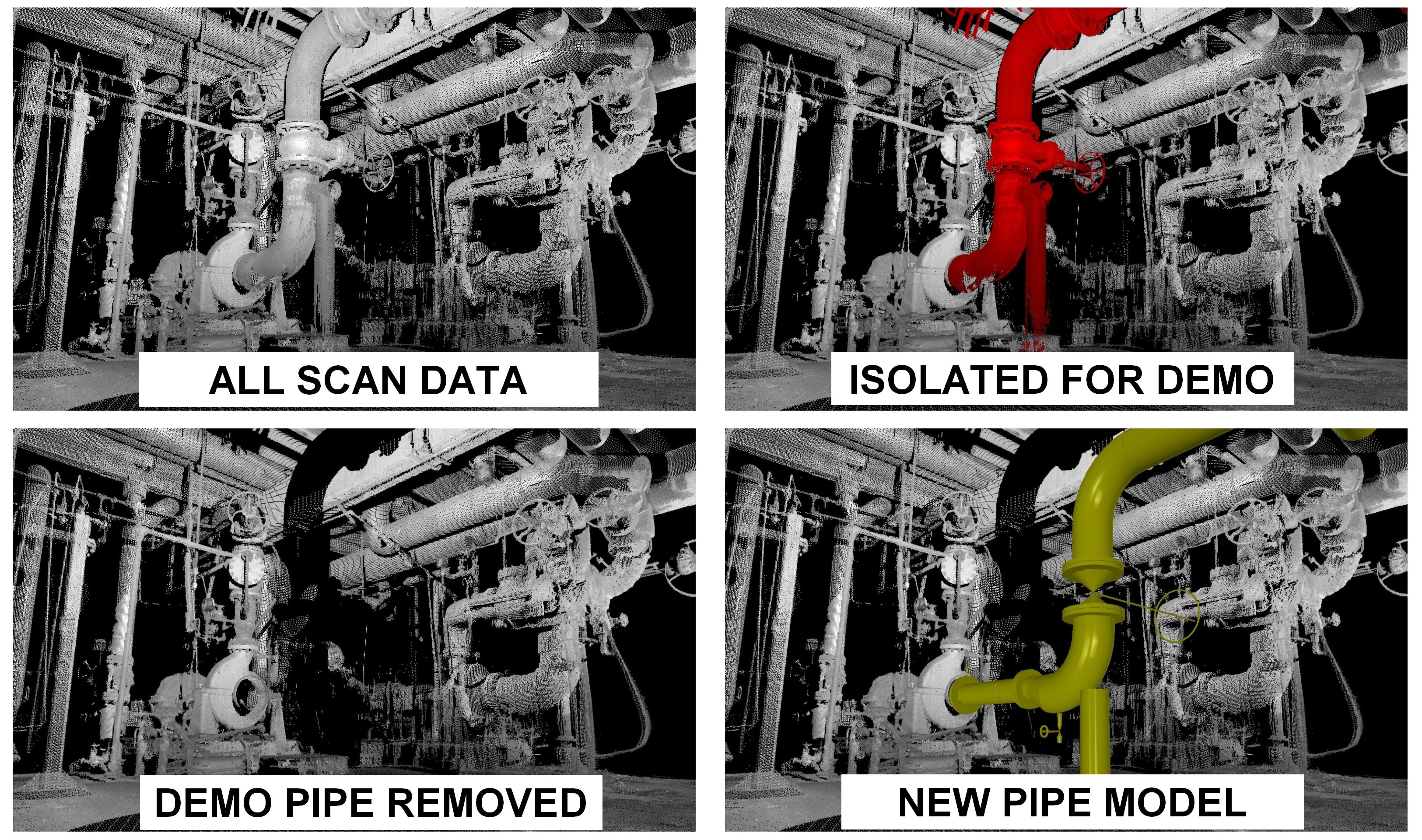
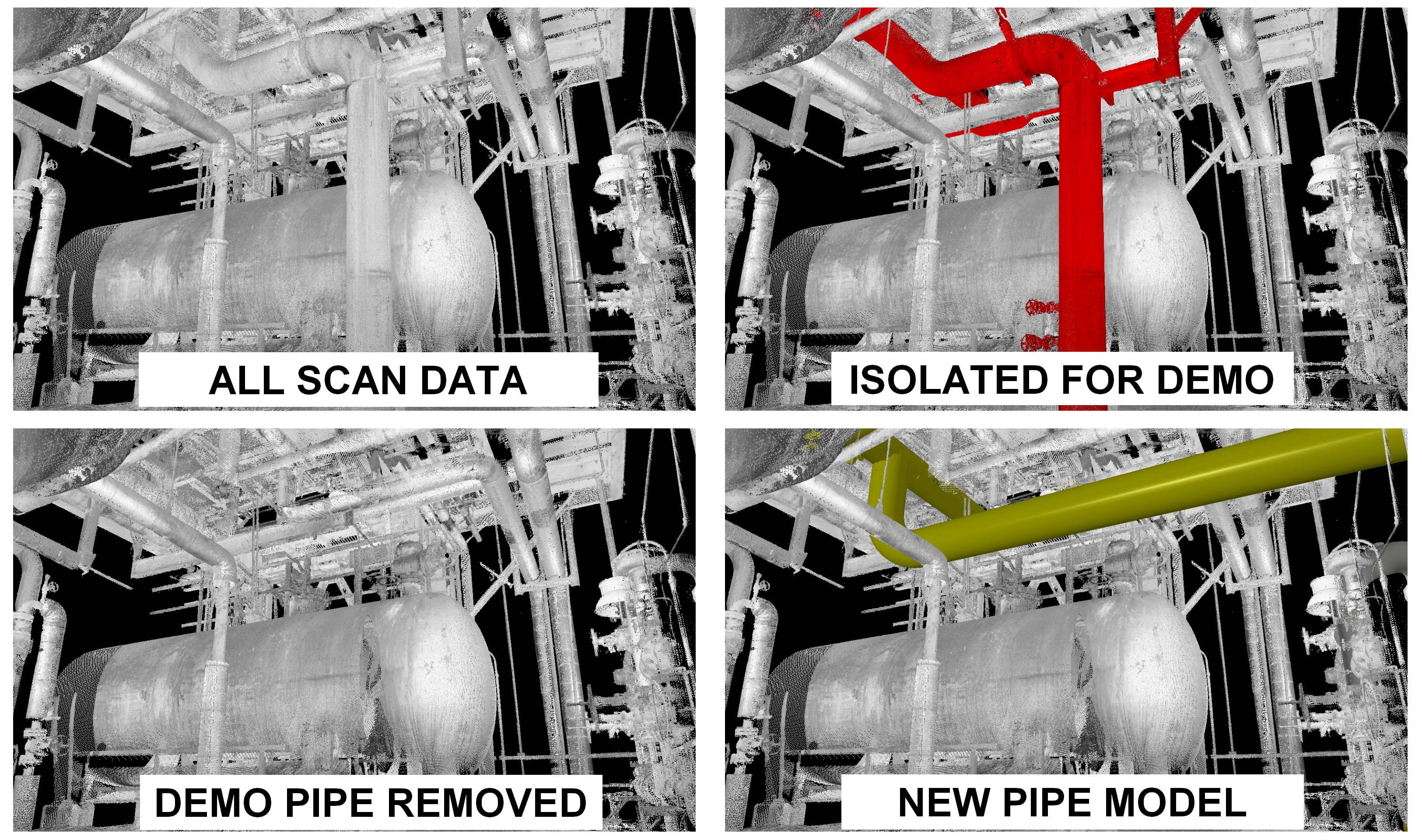
Demo Systems
Based on client provided demarcation points for demolition scope, we can remove those items from the scan data giving a cleaner area for the new design to be placed in the 3D point cloud model.
Measure and Model
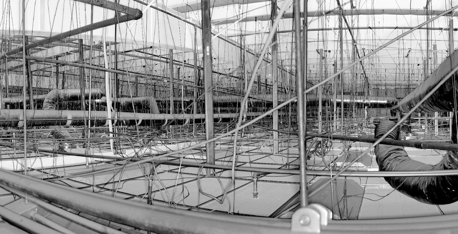
Scan data measurements are superior and more precise than typical "old school" methods of using plumb bobs or measuring tapes. Tight areas such as drop ceilings are cramped and difficult to access.
Using the FARO Focus 3D laser scanner, we are able to capture data and precise measurements of systems such as HVAC, piping, and other hard to reach systems and components inside a drop ceiling. This is done in less time and at a fraction of the cost to the typical approach of evaluating MEP - where designers and/or engineers will go through and confirm drawings by eyeball from a distance, and crawl (often literally) through the suspended maze of piping, wiring, and duct work to measure and document existing MEP systems.
We can take equipment captured in the scan data, and convert it into mesh models. Mesh models include tie-ins and snap-to-points for connecting piping systems. Converting 3D laser scans into mesh models saves time and money on creating 3D models from scratch.
More about 3D Mesh Models from Laser Scans
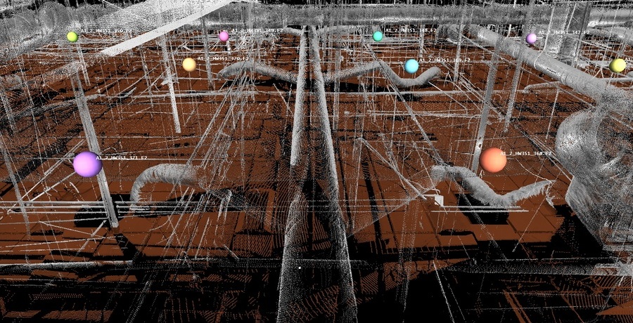
Clash Detection
Many companies large and small, although actively using 3d laser scanning in their workflow may not realize the full benefits of laser scanning. One of those benefits is clash detection.
By placing the model into a scanned 3d environment of existing surroundings, clashes in the design work can be detected and costly unexpected rework can be greatly reduced if not eliminated altogether.
Our process involves following each new pipe or mechanical system and manually inspecting each area for clashes.
When a clash has been located we provide a screen shot of the clash and a spread sheet documenting the following:
- Scan location.
- XYZ site coordinates of the clash.
- Description of the clash.
- Line number (when applicable).
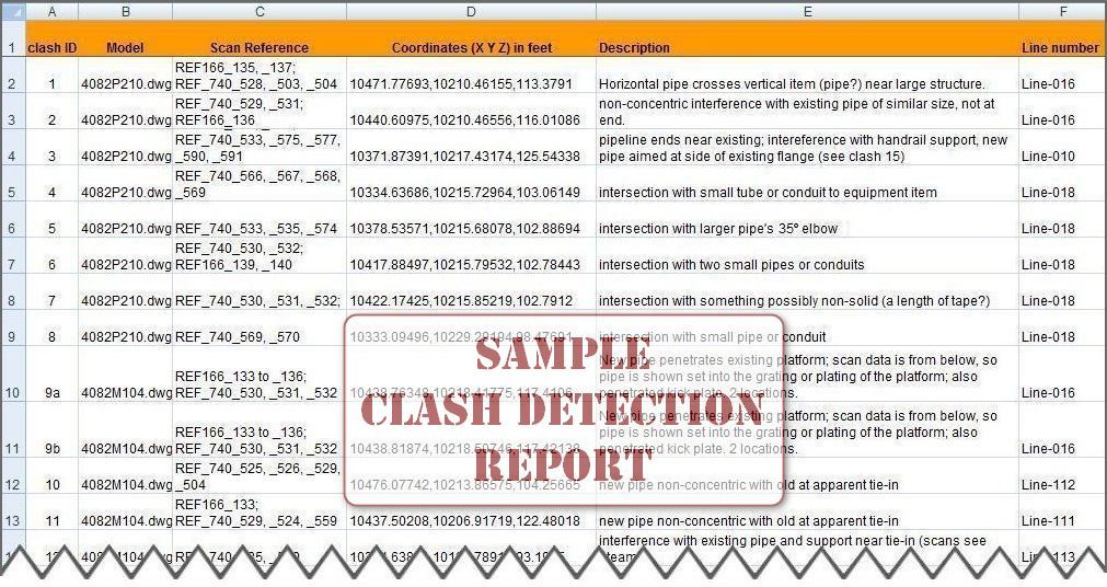 Sample spread sheet listing clashes found when overlaying a CAD model with 3D scan data